
The ESP8266 is a microcontroller that will run you a whopping $7. Affordable and powerful, the ESP8266 is a small serial-to-WiFi microcontroller for simple IoT projects.
In this blog post we’ll create a basic IoT application using the ESP8266 Wi-Fi module. In this case, we’ll build a real-time sensor node, which will read a button and blink an LED in accordance with data transmitted from a remote source.
Many projects incorporating the ESP8266 use it as an external module, communicating over a serial port with a complex set of AT commands. But this module is actually a programmable 32bit MCU with an embedded TCP stack, and if it speaks TCP, it speaks PubNub. With a bit of effort, we can write our own firmware to create a stand-alone, WiFi-enabled device.
Project Overview
For this project, I am using the tiny ESP-01, but any of the modules with access to GPIO0 and GPIO2 will work. The module is loaded with custom firmware, written in C, and compiled using the official SDK from Espressif on a Debian Linux machine. To start, here are a few things you need to get:
- ESP8266 Module
- USB to Serial Module: For programming and debugging (must use 3.3V signals) This is a great one from Sparkfun.
- Development Environment
- PubNub: To get your unique publish/subscribe keys, you’ll first need to sign up for a PubNub account. Once you sign up, you can get your unique keys in the PubNub Developer Dashboard. PubNub’s free Sandbox tier should give you all the bandwidth you need to build and test your IoT app with the pub/sub messaging API.
Feel free to check out the full source code in the project GitHub repository.
With that out of the way, we can get down to business. Like I said before, we will be writing custom firmware to load onto the ESP8266 which can send and receive data to and from any other PubNub enabled device. With 70 official SDKs, that shouldn’t be a problem!
Note: The ESP8266 is not currently an officially supported device, but we’ve created a basic library for use with this module. The library builds off of the PubNub REST API, and we’ll take a deeper look at that later in the blog post.
Hardware
For this demo, I am using the following components:
- Breadboard – Also called a prototyping board; we will use this to connect the other components.
- ESP8266
- Push Button – x2 (normally open, momentary).
- LED – x2 (One is an optional power indicator).
- 10k Resistor – x2 (Color Code: Brown, Black, Orange).
- 1k Resistor – x2 (Color Code: Brown, Black, Red).
- 0.1uF Ceramic Capacitor – This is optional, but does help with performance.
- Jumper Wire – So as to connect stuff together!
Circuit Design
The power source for this project will be the actual USB connection. The USB to Serial module should have its own 3.3V regulator that we can then use to power the ESP8266. The ESP8266 is not 5V tolerant. I cannot stress this enough! You must power it and communicate using 3.3V signals.
Let’s take a look at the circuit.
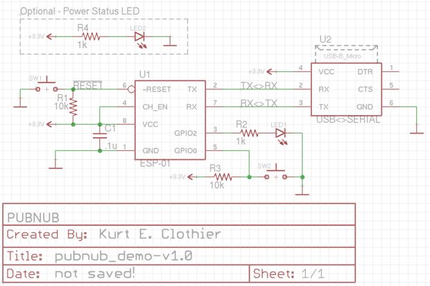
You should notice that the transmit pin (TX) of the ESP goes to the receive pin (RX) of the USB to serial module, and vice versa.
Here is a quick rundown of what every part is doing:
- U1 – ESP8266 module.
- U2 – USB to Serial module.
- C1 – 0.1uF ceramic capacitor – (optional) “Decoupling Capacitor” to increase power line stability.
- R1 – 10k Ohm “Pullup” Resistor – Keeps the chip from resetting by providing a “weak” path to 3.3V.
- SW1 – Normally Open, Momentary Switch (push button) – Resets the chip by connecting “Reset” to Ground.
- R2 – 1k Ohm Resistor – Limits the current through LED1.
- LED1 – An LED we will control with the ESP8266.
- R3 – 10k Ohm “Pullup” Resistor – Keeps GPIO0 “pulled high.”
- SW2 – Normally Open, Momentary Switch (push button) – Connects GPIO0 to Ground.
- R4 – 1k Ohm Resistor – Limits the current through LED2.
- LED2 – Power status indicator (optional).
Wiring It Up
It’s time to connect all of the components together on the breadboard. To start, let’s take a look at the pinout for the ESP module I’m using:
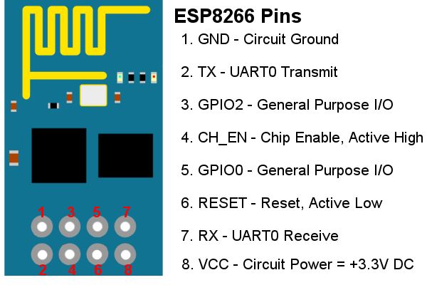
The pinout of your particular USB to Serial module may vary, so you’ll have to consult the user guide for that. Building the circuit on a breadboard should result in something like this:
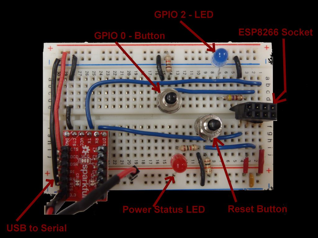
The jumper wire coming off of the USB to Serial module is for the 3.3V power supply because the ‘VCC’ pin is wired to 5V, so I am not using that (for the previously discussed reasons). Also, the ‘ESP8266 Socket’ is just an easy way to plug the module into the breadboard because of it’s pin spacing. It is not required, but making your own might be a good idea.
With the ESP8266 plugged in, the circuit will look like this:
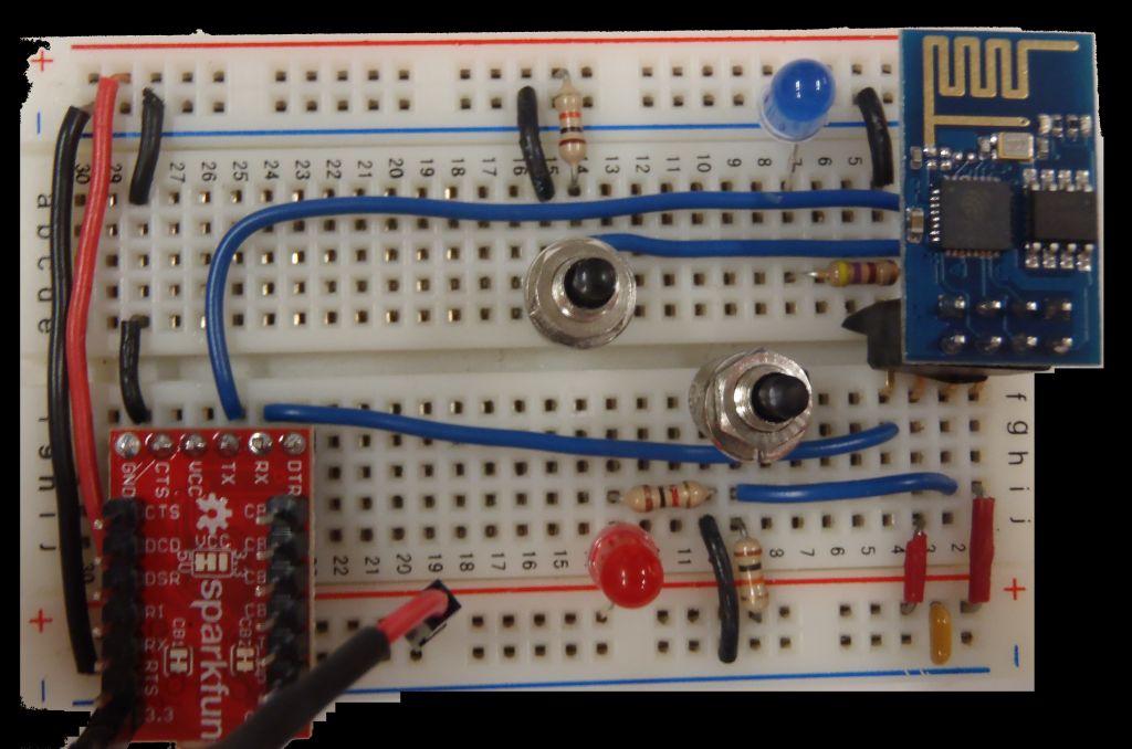
The ESP8266 has a few different operational modes, depending upon the state of some of the pins. If GPIO 0 is held low (connected to ground) when the chip resets, it will enter the ‘UART download boot mode’ which allow us to program the chip’s flash memory. If you recall the circuit, we are using GPIO 0 to read an active low push button, so this works out nicely.
To program the chip, we first push and hold reset, push the GPIO 0 push button, release reset, and finally release the GPIO 0 push button. If you are not used to directly programming these types of chips, this might seem strange to you, but trust me, you will get used to it quickly.
Firmware
With the circuit built, it’s time to check out the code we’ll be installing. If you haven’t yet setup development environment, do so now. This is a tougher part of the project, but there are numerous online tutorials for doing this in various operating systems. If you run into any problems, consult the ESP8266 Community Forum for advice.
Fun Fact: The difference between software and firmware is the actual purpose of the code. Firmware is a subset of software which is installed directly to a chip’s memory rather than on top of some other operating system. For example, VLC Media Player is software, while the code that controls your microwave or the BIOS on your computer is firmware. Embedded devices typically run firmware, but this is not an absolute.
The actual code is in the directory esp8266-helloworld-demo. If you’ve developed your own firmware for this module, the directory structure should look familiar. The main source code is found in user, while included header files are place in include. The PubNub source code is found in the pubnub directory. Compiled builds are found in build, and the files to be written to memory are in firmware.
Operation
When first powered on, LED1 will flash twice per second. This will continue until the device connects to the Internet. At this time, a connection to PubNub will be established. This demo incorporates both publishing and subscribing to a channel.
Unfortunately, publish events cannot take place until a subscribe event takes place or times out. This is due to limitations in single-threaded devices. The provided library can be adjusted for a particular need (such as only publishing, or automatically subscribing) or be reworked to incorporate threading if a different SDK is used.
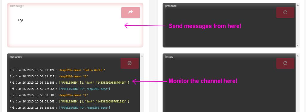
The device will subscribe to the channel “esp8266-demo”. Any other device writing to this channel can send commands to our ESP8266! For this demo, we will use the PubNub Developer’s Console, but any mobile app, web page, or other application can be used.
A message of “1” will turn on LED1, while “0” will turn it off. Pushing SW2 will request a publish which will take place at either the next subscription message received or a timeout, due to the limitations previously discussed. Removing the “subscribe” section of code or otherwise adjusting the overall program flow will allow for real-time publishing.
Makefile
I have provided a Makefile which will build the outputs and program a connected device; however, to use it you will have to manually adjust the location of your toolchain paths. If you have installed the toolchain based on the instructions I previously linked to, there should be minimal changes required.
The following primary targets are available for use:
- all – this is default.. it will: clean, build, clean
- build – this will: clean, build
- clean – this will: clean
- flash – this will: flash the chip
For basic compilation checks, simply issuing a ‘make’ command is quick and easy. To actually program the chip, you will have to issue ‘make build’ followed by ‘make flash’ (or possibly ‘sudo make flash’). A working build is included in the repository, so once you have the Makefile adjusted, you can use it to flash your chip; however, until you manually configure your WiFi settings, the device will be unable to connect to the internet.
Main
When directly programming common microcontrollers like the Atmel AVR line, you can create a main function containing an internal “forever loop.” This is not the case with the ESP8266. This module uses hooks, similar to Arduino, so the compiler will expect a few defined functions. After that, you can schedule a timer to handle repeated tasks.
The most common hooks in use are:
Othwerwise, you are free to write your own functions and call them like a normal C program. The “IFA” attribute is actually a macro I defined in include/esp8266.h as:
If a function is prefixed with IFA, it is written to flash which is mapped to ROM. Without this attribute, the function will end up in the instruction RAM segment, which is faster, but will fill up quickly. If at all possible, always use the IFA attribute. This header file also includes most all of the SDK libraries commonly used as well as remapping a few common C functions (like printf) to the version required by the Espressif SDK (os_printf).
Lastly, it defines a simple debug printing macro which can be used to selectively print statements when a certain value is defined, which it is in theinclude/user_config.h file.
Inside of the user_init() function, we will initialize the UART connection, setup the GPIO pins, and connect to WiFi. The values ofSSID and SSID_PW are define in include/user_config.h. You must set these values to the corresponding SSID and password for your home WiFi connection! The overall code flow goes something like this:
- Initialize UART
- Initialize GPIO
- Initialize PubNub
- Connect to network (pause here until connection established)
- Connect to PubNub
- Monitor button (SW2) and control LED1 based on messages received.
PubNub Library
The provided library defines the following functions inpubnub/pubnub.h.
The usage of each of these functions is clearly shown inuser/user_main.c. I have also supplied the full C source code instead of a typical lib file, so feel free to poke around inside and alter the code to be more specific to your tasks.
The primary force behind the library is the PubNub REST API. An HTTP Get request string is build and used for all functionality. Using these basic building blocks, other PubNub real-time messaging functionality can be added including Presence, History, and Security.
Using the PubNub Developer Debug Console
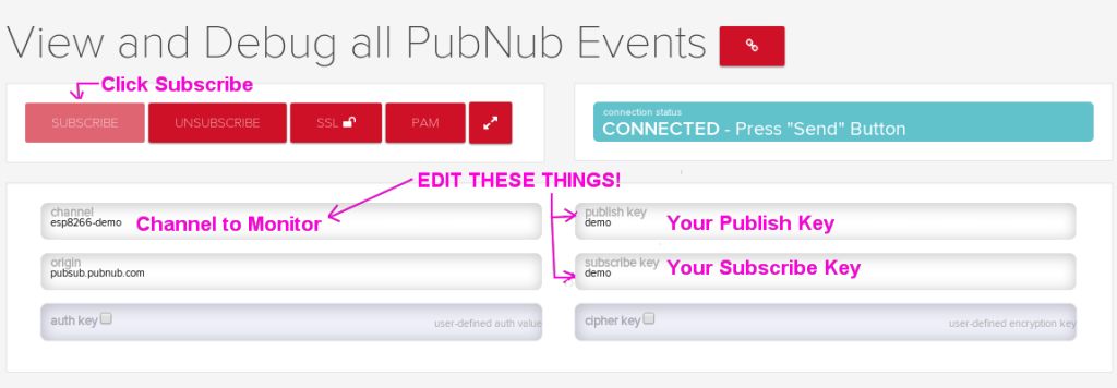
Instead of developing a web interface from scratch, you can easily test the different components of your IoT application using the PubNub Developer Console. Using your unique publish/subscribe keys, you can publish and subscribe to your channel.
First subscribe:
You can then send messages to the channel as well as monitor the channel for all messages published.
Serial Debugging
If you plan on modifying the code to do whatever you like, you will want to make use of the DEBUG_PRINT() statements scattered about the library. These will print information through the serial port whenever various events take place. The UART is initialized to a baud rate of 9600, but this is easily modified in include/user_config.h.
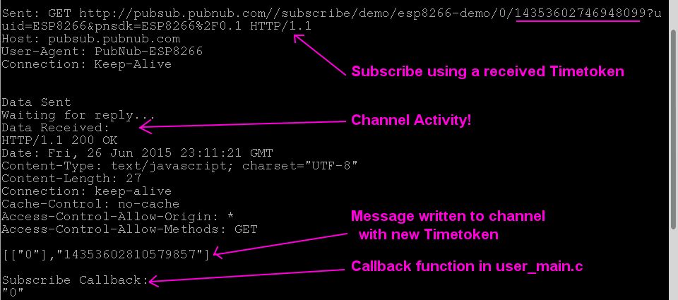
In Linux, I am using the program gtkterm for serial bugging. A typical run through of this demo will look something like this:
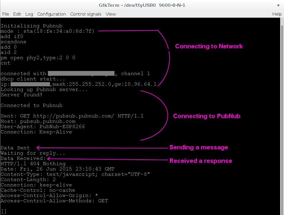
After this initial message is sent, PubNub will send an empty response. Now, we can subscribe to a channel. The first subscribe call will use a Timetoken of ‘0’. PubNub will respond with a valid timetoken which should be used in the next subscribe call.
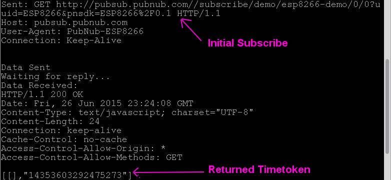
From here on, every response after a subscribe will contain a new Timetoken. This new Timetoken should always be used in the next subscribe call. After a subscribe call, the program will wait for a response or a timeout. When a message is received, it will be displayed, and the user defined subscribe callback function inuser_main.c will be called.
If the button on GPIO 0 is pushed, a publish request will be made. You should see a “Waiting on subscription(s)” message. The publish will then happen after the next message is received or a timeout occurs (in roughly 300 seconds). After the publish event, a new subscribe call using the last Timetoken is made again.
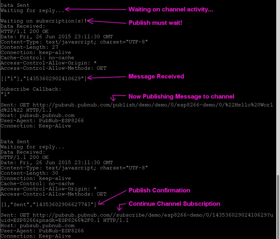
Note, that any messages sent from this device to a subscribed channel will be received on this device as well.

Wrapping Up
That’s it! We’ve just built a simple IoT application with the ESP8266 module with flexible and fast bidirectional messaging. You can communicate with your device(s) in real time from any other PubNub enabled device in the world!
Even better, the library used in this tutorial can also be customized for your specific needs. Functionality can easily be added or removed, and the basics shown here can really be applied to any other chip you want to use that has TCP capabilities. So go forth, and create something amazing! Just be sure to let us know what you come up with.